Agenda
- Requirements
- Voltage Setup
- Voltage Measurement
- Radio Test Setup
- Radio Test
- Conclusion
This initial test can be operated right after the fabrication of the PCB.
Requirements
- Hardware
- Software:
- openocd: to flash the FPGA
- Amarisoft software: to run tests
Voltage Setup
TODO: Picture
Prepare to power on the PCB as shown in the photo.
Configure the lab power supply with: 24V, 200mA max, to ensure there is no severe short circuits.
Install the PCB in the shield box, make sure that the board is well attached to the thermal paste.
Voltage Measurement
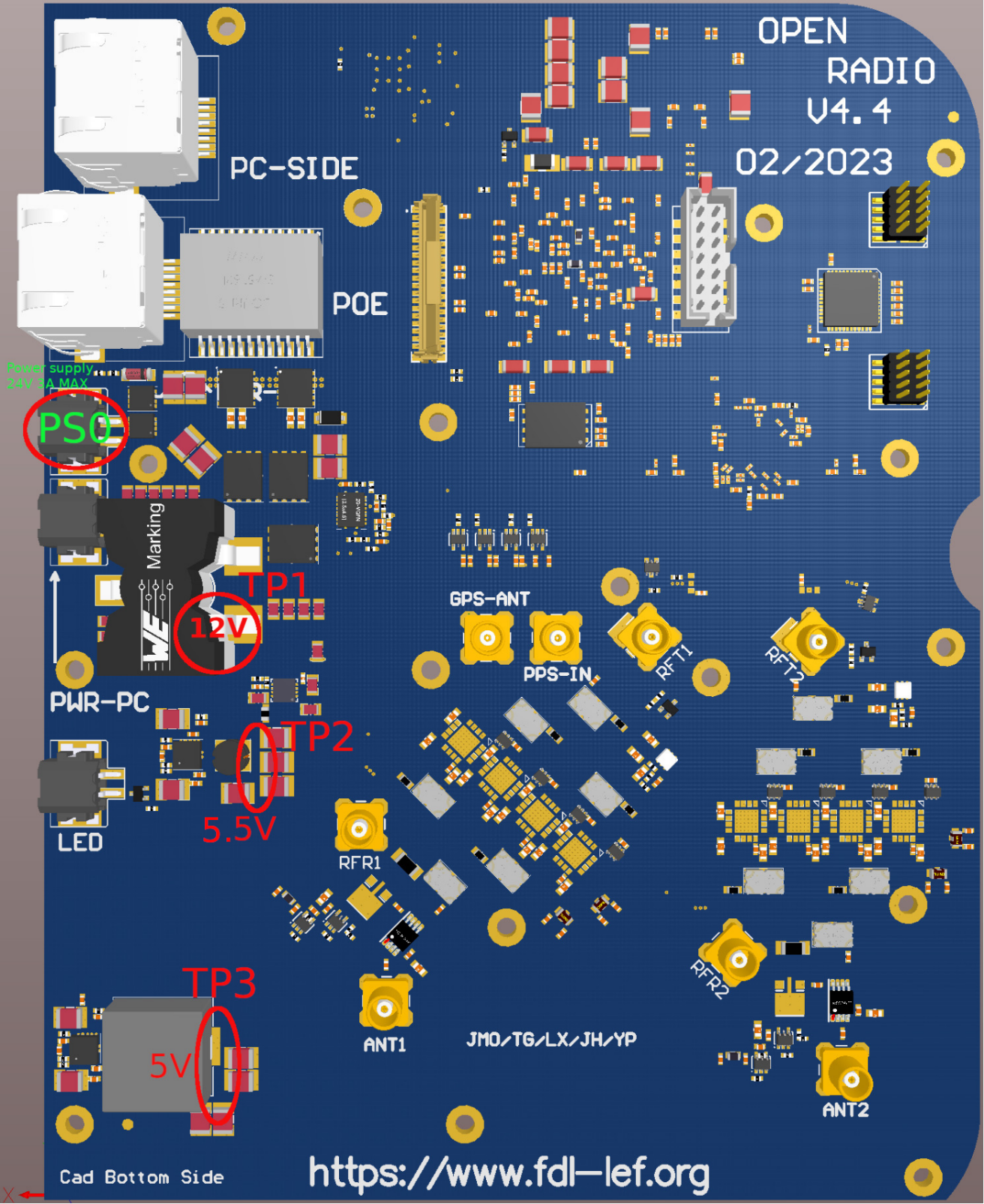
Bottom Side
- Connect power cable to the connector PS0 without connecting to the mini PC. Set the power to 24V 200mA and turn on the power supply. If there is no severe short circuit, the current is supposed to be around 105mA when the FPGA is not flashed.
- Test the voltage on each Test point.
- PS0:
- Power the PCB on with 24V 200mA max for the first time without connecting the mini PC.
- Operation/Test mode: 24V 3A max.
- TP1: 12V
- TP2: 5.5V
- TP3: 5V
*TP: test point
*PS0: Power supply

Top side
- TP4: 1V8
- TP5: 1V8
- TP6: 2V5
- TP7: 1V2
- TP8: 3V3
- TP9: 1V3
- TP10: 3V3
Radio Test Setup
Hardware setup


1. Disconnect power cable on PS0.
2. Connect the PC and the PCB as the picture shown above. There are 3 cables linking the PC and the PCB : Ethernet cable, Power cable, FFC cable. (Attention: the power cable of PC is connected to the port PWR_PC)
3. Connect the PoE cable. The power input for the entire device is via PoE.
4. Connect customized MCX cables to the two output channels ANT1 and ANT2 on one side and on the callbox on the other side as picture shown above.
Flash the FPGA firmware
Follow rapidspace-HowTo.Flash.FPGA.Firmware.Of.ORS.PCB procedure.
Check the connection between mini PC and the PCB
- make sure to totally power off and on again after flashing the FPGA
- ssh to the mini PC connected to the PCB
- make sure Amarisoft software is installed
root@orsLAB:~# ls ~/trx_sdr
api         config.probe  config.ue    cpri_sniffer  install.sh  libc_wrapper_sdr.so  license.pdf  ReleaseNotes-trx_sdr.txt  sdr_play      sdr_test  trx_sdr.so
config.enb  config.scan   config.view  doc           kernel      libsdr.so            license.txt  rrh_check.sh              sdr_spectrum  sdr_util
If you don't have trx_sdr folder, ask RapidSpace team.
- insmod the kernel driver
root@orsLAB:~# cd ~/trx_sdr/kernel
root@orsLAB:~/trx_sdr/kernel# ./init.sh
root@orsLAB:~/trx_sdr/kernel#
- make sure the PCB board is recognized
root@orsLAB:~# dmesg | grep sdr
[   19.289344] sdr: loading out-of-tree module taints kernel.
[   19.289378] sdr: module verification failed: signature and/or required key missing - tainting kernel
[   19.289655] sdr Probing device
[   19.289667] sdr 0000:01:00.0: enabling device (0000 -> 0002)
[   19.294534] sdr CDCM6208_initialize (VCXO 38.4MHz)
[   21.293209] sdr cdcm6208: timeout while waiting for PLL lock
[   21.333269] sdr PCI device 01:00.0 assigned to minor 0, type=RF_SDR50 (rev 0)
[   21.333273] sdr FPGA Revision: 2021-10-8
if you see only the 2 first lines, it means the FPGA of the PCB is not correctly flashed or there is a problem in the connection between the PC and the PCB. Try to refix the miniPCIe ribbon and power off/on again.
Radio Test
Note 1: this code is currently not public but will be soon. This part will surely be adapted.
Note 2: for now, the tools from Amarisoft must be changed on the ORS because the RF switch used in TDD is not correctly setup by sdr_spectrum tool.
1. Make sure you have ssh without password to the miniPC ("orsLAB" in our example) and the callbox ("callbox-003" in our example).
2. In directory ~/ors-utils-private/PCB_auto_test/, run command: (Read Warning before running the command)
./auto_test.bash orsLAB callbox-003 ~/workspace/ors-utils-private/matlab/signal-generation/waveform/LTE-31-20MHzBP_SR3072-FDD-ADJUSTED.bin ~/workspace/ors-utils-private/python_RF/FFTplotIQFiles.py 2600e6 D11
Warning :
- Change the ~/workspace/ors-utils-private to a correct directory that matches your own folder location.
- Change [2600e6] parameter to the frequency corresponding to the band frequency. (e.g. Band42 = 3500e6)
- Modify board name [D11] to a correct name that matches the PCB, the board name will be printed in the test result to distinguish different PCBs.
3. Every time change the PCB, please input the correct frequency and board name in the command.
Notes :
- The measurement of TX power is done on both channel 1 and 2 with TX gain 65 and 85.
- The measurement of RX power is done on both channel 1 and 2 with TX gain of 89 dB.
- Test results of TX will be printed in "RESULT" in miniPC(orsLAB), the test result of RX will be printed in callbox.
Example of test result :
TX power :

RX power :

Conclusion
If the PCB works normally, the test results of PCBs in same band are similar. The values differ in different band frequency.
In result of TX power, the first value of each line is the main power,
when TX gain is 65, the main TX power should be:
* for band 39: between 0 and 5
* for band 38: between -10 and -5
* for band 42: between -20 and -15
* for band 43: between -18 and -12
when TX gain is 85, the main TX power should be:
* for band 39: between 18 and 20
* for band 38: between 10 and 15
* for band 42: between 0 and 5
* for band 43: between 0 and 7
In result of RX power, the first value indicates the main power,
When RX gain is 89, the main RX power should be:
* for band 39: between 30 and 32
* for band 38: between 26 and 28
* for band 42: between 19 and 22
* for band 43: between 15 and 19
These ranges are defined according the setup in Rapid.Space office lab, the correct value range may differ depending on the test hardware setup.